Furnace C40 consists of twelve 100 kW burners recuperative technology and 1.200 °C maximum operating tem- perature. Recuperative burners enable thermal energy exchange between combustion air and exhaust gases by mean of counter flow fluid motion across ceramic (or metallic) fins. This configuration enhances air pre-heating and it is recommended for heat treatment applications where temperature uniformity is mandatory. Recuperative burners allow energy savings of 15 – 20% compared to cold air.
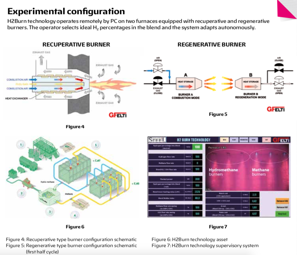
Furnace C47 has 1 couple of 300 kW burner regenerative type and 1.300 °C maximum operating temperature. Regenerative burners consist of a ceramic recuperator embedded in each unit. The working principle consists of having a couple of burners that works alternatively. When one burner is working (i.e. first part of cycle), the other absorbs thermal energy coming from exhaust gases into its ceramic body. This energy is then transferred to combustion air from ceramics when combustion cycle shifts. Regenerative technology is recommended for high temperature applications like forgings and reheating furnaces. Achievable energy saving is 40 – 50% compared to cold air technology. Figure 4 and Figure 5 offer an appreci- ation of these solutions entirely manu- factured by GF-ELTI.
Combustion apparatus of each fur- nace is modified to have half thermal output powered by hydromethane, whilst the other part works “traditionally” with methane. Specifically, 3 recuperative burners from a row of six are upgraded to operate with hydrogen (i.e. furnace C40) and 1 regenerative burner of the couple too (i.e. furnace C47). The objective of the test is to critically analyze differences in flame generation as well as its stability, and to verify correct burner lightning time with hydromethane. This test is an opportunity to critically review some new instrumentation required by hydrogen, such as valves, sensors, flame detection units, etc. Having two different types of fuels for combustion allows also qualitative considerations on flame visibility.
Test configuration
Figure 6 shows H2Burn configuration and its key elements. For the purpose of this test, Hydrogen cylinder packs (1) are selected. Other options like tube trailers and electrolyser could not be as competitive as cylinder packs. They could not allow sufficient flexibility to cope with intermittency due to test set up and adjustments. The Italian company SICO SpA guaranteed the continuous supply of hydrogen packs during test. Normally, hydrogen is pressurised at 200 bar. This value needs reduc- tion as low as 0,8 bar, a common operating value for furnaces. To do so SICO SpA developed a first stage pres- sure reduction unit to make pressure drop from 200 bar to 10 bar, then GF-EL- TI conceived the second stage pressure reduction unit (2) to reach 0,8 bar.
After pressure reduction, hydrogen flows into FDBU (3) to meet methane pipeline (4). Inside FDBU blending takes place to generate hydromethane. This unit allows modifications to hydrogen percentages into blend in real time (10÷100% H2). It consequently enables automatic flowrates regulation at burner inlet assuring constant thermal power output. To do so some PLC modifications were necessary. The original “methane” working logic is upgraded by modifying combustion principles so as the equipment secures exact flow- rates. These changes are essential be- cause of the natural differences of hy- drogen and methane heating values.
Process variables controlled
Furnaces (5) are entirely controlled via SCADA. Figure 7 shows the logic developed by GF-ELTI that allows remote working. It is possible to set real time hydrogen percentages into blend by PC. The supervisory spreadsheet displays many process variables, such as fluids flowrates, their current heating value, CO2 generated from combustion, and operation costs. Not only numbers and figures, cameras inside furnaces help the operator to observe how flames be- have during combustion and to appre- ciate differences in colour, shape, and dimension.
This section focuses on the findings of hydromethane operation in combustion equipment. Some experiments were carried out to investigate blend behaviour in different environments and working conditions to get in-depth information. The report provides a general understanding of hydrogen benefits and limitations for the energy transition.


